The “Polarization Scam”: When a Laser Hits Your Mirror at an Angle
2026-6-2
I.A common 'train wreck' scenario
You bought a reflector from a supplier; the specifications state a reflectivity of 99.9%. You install it in the optical path, shine a laser on it, and the actual reflectivity is only 96%. Your first reaction: the supplier misrepresented the specifications.
The supplier sends a factory inspection report: the testing conditions were correct, and the actual reflectivity is indeed 99.9%. Neither side falsified the data. Where did the problem lie? Most likely, you used the wrong polarization.
This is not an uncommon occurrence. Similar scenarios happen repeatedly in optical laboratories and production lines. The root cause is that many people treat reflectivity as a fixed value, but in reality, reflectivity is extremely sensitive to polarization.
II. Why is reflectivity not constant?
Light is an electromagnetic wave. The direction of the electric field vibration is the polarization direction. When light shines on the surface of a mirror, the reflectivity depends on the orientation of the electric field relative to the incident plane. Here are two basic definitions:
S-polarization: The direction of the electric field vibration is perpendicular to the incident plane.
P-polarization: The direction of the electric field vibration is parallel to the incident plane.
The incident plane is the plane defined by the incident ray and the mirror normal. The same mirror will have different reflectivities for S-polarization and P-polarization. This difference is not a material defect, but a physical law determined by the boundary conditions of the electromagnetic field. Solving Maxwell's equations at the interface of a medium directly yields Fresnel's formulas, and the formulas for S-polarization and P-polarization are different:
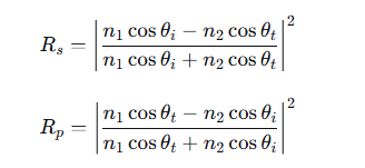 Where n₁ and n₂ are the refractive indices of the two media, θᵢ is the angle of incidence, and θ_t is the angle of refraction. The two formulas are not equal, therefore the reflectivities of the two polarizations are naturally different.
III. Angle of Incidence: Amplifier of Difference
At normal incidence (0° angle of incidence), the distinction between S-polarized (S) and P-polarized (P) reflectivity becomes meaningless, as both have equal reflectivity. However, once the light is incident at an angle, the reflectivity of S-polarized and P-polarized light diverges immediately.
For example, using a common aluminized mirror at a 45° angle of incidence, in the visible light band:
S-polarized reflectivity: approximately 92%
P-polarized reflectivity: approximately 85%
A difference of 7 percentage points. If you are using a laser with a high proportion of P-polarization, the overall reflectivity will be lowered. This is why the 99.9% on the specification sheet (usually measured at normal incidence or under a specified polarization) does not match the 96% you measured.
The polarization separation is even more pronounced in dielectric mirrors. Highly reflective dielectric films rely on multilayer interference effects, and the interference conditions differ for S-polarized and P-polarized light. At a 45° angle of incidence, the reflection bandwidth of S-polarized light is much wider than that of P-polarized light; the high-reflectivity region can cover the entire visible light band, while P-polarized light begins to drop off at the edge of the bandwidth.
IV. Brewster's Angle: The Vanishing Point of P-Polarization
An extreme case of polarization is the Brewster angle.
When the angle of incidence satisfies θ_B = arctan(n₂/n₁), the reflectivity of P-polarized light drops to zero. At this angle, P-polarized light is completely transmitted, and only S-polarized light is reflected.
For glass with a refractive index of 1.5, the Brewster angle is approximately 56°. Near this angle, the reflected light becomes almost purely S-polarized. If you use a plain glass plate as a beam splitter and place it at the Brewster angle, you can achieve polarized beam splitting without any coating.
This effect has practical applications in laser resonator cavities. The Brewster window utilizes the characteristic that P-polarization has zero reflection loss at the Brewster angle, allowing the laser to oscillate in P-polarization within the cavity, minimizing window loss. S-polarization, however, is lost due to reflection from the window and cannot oscillate. As a result, the laser output is inherently linearly polarized.
V. Polarization Traps of Highly Reflective Dielectric Films
For multilayer dielectric high-reflectivity mirrors, the polarization effect not only reduces reflectivity at specific angles, but more subtly, the polarization state is altered during reflection.
When the incident light is linearly polarized but contains S and P components, after reflection by the dielectric film, the S and P components not only have different amplitudes but also different phase delays. The phase difference between the two components after reflection differs from their initial phase, causing the linear polarization to become elliptic polarization.
This effect can have serious consequences in the following scenarios:
Optical path deflection: The laser beam travels in a "Z" shape, passing through multiple 45° mirrors. Each mirror introduces a small S-P phase difference, which accumulates until the polarization state is completely out of control. The originally linearly polarized laser becomes elliptically polarized at the target location, causing subsequent polarization beam splitters, electro-optic modulators, and interferometers to malfunction.
Resonant cavity design: The polarization phase dispersion of the intracavity mirrors affects the stability and pulse width of the mode-locked pulse. The group delay dispersion and polarization-dependent phase of dielectric mirrors within a high reflection bandwidth are among the core parameters for femtosecond laser design.
Interferometry: Interferometers rely on the coherent superposition of two beams. If one beam experiences a polarization phase disturbance from a mirror, its polarization state changes upon return, reducing interference contrast and compromising measurement accuracy.
VI. How to avoid polarization traps
First, clarify the polarization requirements of your system.
Before selecting a reflector, determine whether your laser is linearly polarized, circularly polarized, or randomly polarized. Understand whether subsequent optical paths have requirements regarding polarization state. If the entire system is polarization-independent (e.g., only power is a concern, not polarization state), the impact of polarization separation is relatively controllable. If it's a polarization-sensitive system (with interferometers, polarization beam splitters, or electro-optic crystals), the polarization behavior of each reflector must be considered.
Second, review the test conditions in the datasheet.
Reflectivity is not an independent value. It is tied to the angle of incidence and polarization state. Reputable manufacturers will specify the test conditions, such as "R > 99.9%, 0° incident, random polarization" or "R_s > 99.5%, 45° incident." Once you have the datasheet, check if the test conditions match your usage conditions. A lens used at 45° cannot be budgeted based on a 0° reflectivity.
Third, select the coating system design based on the angle of incidence.
At small incident angles (<15°), the difference between S and P is usually negligible, and a general-purpose coating system can meet the requirements. For large-angle incidence (30°~60°), a film system optimized for the specific angle and polarization must be used. For example, a mirror specifically designed for 45° S-polarization, or a broadband mirror with low polarization sensitivity. If the system requires similar S and P reflectivities, a metal-dielectric hybrid film system can be used, leveraging the low polarization sensitivity of the metal film and then using a dielectric film to increase the overall reflectivity.
Fourth, manage polarization states in the optical path.
If there are multiple mirrors in the optical path, try to keep their incident surfaces aligned. Phase delays in S and P accumulate in the same direction and can be pre-compensated. If the incident surfaces of the mirrors are perpendicular, the definitions of S and P are interchanged on each surface, resulting in complex and difficult-to-compensate cumulative polarization effects.
Fifth, verify with measurements, don't just rely on budgets.
Reflectivity loss and polarization state changes are multiplicative and cumulative effects in multi-mirror systems. Budgeting during the design phase is necessary, but the final verification method is measurement. The polarization state was measured at the end of the optical path using a polarization analyzer, and the reflection loss was checked surface by surface using an optical power meter to ensure that the actual performance at each step was consistent with the design expectations.
VII. Summary
The reflectivity of a mirror is not an absolute constant. It varies with the polarization state and the angle of incidence. This variation is not a manufacturing defect but a fundamental behavior of electromagnetic waves at a dielectric interface.
Key points:
S-polarization and P-polarization have different reflectivities, and the difference increases with the angle of incidence.
At the Brewster angle, P-polarization has zero reflectivity and can be used for natural polarization beam splitting.
Dielectric mirrors introduce S-P phase difference, altering the polarization state of the reflected light.
Mirror selection must match the actual angle of incidence and polarization conditions.
Polarization effects accumulate in multi-mirror optical paths, requiring end-to-end management.
You bought a reflector from a supplier; the specifications state a reflectivity of 99.9%. You install it in the optical path, shine a laser on it, and the actual reflectivity is only 96%. Your first reaction: the supplier misrepresented the specifications.
The supplier sends a factory inspection report: the testing conditions were correct, and the actual reflectivity is indeed 99.9%. Neither side falsified the data. Where did the problem lie? Most likely, you used the wrong polarization.
This is not an uncommon occurrence. Similar scenarios happen repeatedly in optical laboratories and production lines. The root cause is that many people treat reflectivity as a fixed value, but in reality, reflectivity is extremely sensitive to polarization.
II. Why is reflectivity not constant?
Light is an electromagnetic wave. The direction of the electric field vibration is the polarization direction. When light shines on the surface of a mirror, the reflectivity depends on the orientation of the electric field relative to the incident plane. Here are two basic definitions:
S-polarization: The direction of the electric field vibration is perpendicular to the incident plane.
P-polarization: The direction of the electric field vibration is parallel to the incident plane.
The incident plane is the plane defined by the incident ray and the mirror normal. The same mirror will have different reflectivities for S-polarization and P-polarization. This difference is not a material defect, but a physical law determined by the boundary conditions of the electromagnetic field. Solving Maxwell's equations at the interface of a medium directly yields Fresnel's formulas, and the formulas for S-polarization and P-polarization are different:
III. Angle of Incidence: Amplifier of Difference
At normal incidence (0° angle of incidence), the distinction between S-polarized (S) and P-polarized (P) reflectivity becomes meaningless, as both have equal reflectivity. However, once the light is incident at an angle, the reflectivity of S-polarized and P-polarized light diverges immediately.
For example, using a common aluminized mirror at a 45° angle of incidence, in the visible light band:
S-polarized reflectivity: approximately 92%
P-polarized reflectivity: approximately 85%
A difference of 7 percentage points. If you are using a laser with a high proportion of P-polarization, the overall reflectivity will be lowered. This is why the 99.9% on the specification sheet (usually measured at normal incidence or under a specified polarization) does not match the 96% you measured.
The polarization separation is even more pronounced in dielectric mirrors. Highly reflective dielectric films rely on multilayer interference effects, and the interference conditions differ for S-polarized and P-polarized light. At a 45° angle of incidence, the reflection bandwidth of S-polarized light is much wider than that of P-polarized light; the high-reflectivity region can cover the entire visible light band, while P-polarized light begins to drop off at the edge of the bandwidth.
IV. Brewster's Angle: The Vanishing Point of P-Polarization
An extreme case of polarization is the Brewster angle.
When the angle of incidence satisfies θ_B = arctan(n₂/n₁), the reflectivity of P-polarized light drops to zero. At this angle, P-polarized light is completely transmitted, and only S-polarized light is reflected.
For glass with a refractive index of 1.5, the Brewster angle is approximately 56°. Near this angle, the reflected light becomes almost purely S-polarized. If you use a plain glass plate as a beam splitter and place it at the Brewster angle, you can achieve polarized beam splitting without any coating.
This effect has practical applications in laser resonator cavities. The Brewster window utilizes the characteristic that P-polarization has zero reflection loss at the Brewster angle, allowing the laser to oscillate in P-polarization within the cavity, minimizing window loss. S-polarization, however, is lost due to reflection from the window and cannot oscillate. As a result, the laser output is inherently linearly polarized.
V. Polarization Traps of Highly Reflective Dielectric Films
For multilayer dielectric high-reflectivity mirrors, the polarization effect not only reduces reflectivity at specific angles, but more subtly, the polarization state is altered during reflection.
When the incident light is linearly polarized but contains S and P components, after reflection by the dielectric film, the S and P components not only have different amplitudes but also different phase delays. The phase difference between the two components after reflection differs from their initial phase, causing the linear polarization to become elliptic polarization.
This effect can have serious consequences in the following scenarios:
Optical path deflection: The laser beam travels in a "Z" shape, passing through multiple 45° mirrors. Each mirror introduces a small S-P phase difference, which accumulates until the polarization state is completely out of control. The originally linearly polarized laser becomes elliptically polarized at the target location, causing subsequent polarization beam splitters, electro-optic modulators, and interferometers to malfunction.
Resonant cavity design: The polarization phase dispersion of the intracavity mirrors affects the stability and pulse width of the mode-locked pulse. The group delay dispersion and polarization-dependent phase of dielectric mirrors within a high reflection bandwidth are among the core parameters for femtosecond laser design.
Interferometry: Interferometers rely on the coherent superposition of two beams. If one beam experiences a polarization phase disturbance from a mirror, its polarization state changes upon return, reducing interference contrast and compromising measurement accuracy.
VI. How to avoid polarization traps
First, clarify the polarization requirements of your system.
Before selecting a reflector, determine whether your laser is linearly polarized, circularly polarized, or randomly polarized. Understand whether subsequent optical paths have requirements regarding polarization state. If the entire system is polarization-independent (e.g., only power is a concern, not polarization state), the impact of polarization separation is relatively controllable. If it's a polarization-sensitive system (with interferometers, polarization beam splitters, or electro-optic crystals), the polarization behavior of each reflector must be considered.
Second, review the test conditions in the datasheet.
Reflectivity is not an independent value. It is tied to the angle of incidence and polarization state. Reputable manufacturers will specify the test conditions, such as "R > 99.9%, 0° incident, random polarization" or "R_s > 99.5%, 45° incident." Once you have the datasheet, check if the test conditions match your usage conditions. A lens used at 45° cannot be budgeted based on a 0° reflectivity.
Third, select the coating system design based on the angle of incidence.
At small incident angles (<15°), the difference between S and P is usually negligible, and a general-purpose coating system can meet the requirements. For large-angle incidence (30°~60°), a film system optimized for the specific angle and polarization must be used. For example, a mirror specifically designed for 45° S-polarization, or a broadband mirror with low polarization sensitivity. If the system requires similar S and P reflectivities, a metal-dielectric hybrid film system can be used, leveraging the low polarization sensitivity of the metal film and then using a dielectric film to increase the overall reflectivity.
Fourth, manage polarization states in the optical path.
If there are multiple mirrors in the optical path, try to keep their incident surfaces aligned. Phase delays in S and P accumulate in the same direction and can be pre-compensated. If the incident surfaces of the mirrors are perpendicular, the definitions of S and P are interchanged on each surface, resulting in complex and difficult-to-compensate cumulative polarization effects.
Fifth, verify with measurements, don't just rely on budgets.
Reflectivity loss and polarization state changes are multiplicative and cumulative effects in multi-mirror systems. Budgeting during the design phase is necessary, but the final verification method is measurement. The polarization state was measured at the end of the optical path using a polarization analyzer, and the reflection loss was checked surface by surface using an optical power meter to ensure that the actual performance at each step was consistent with the design expectations.
VII. Summary
The reflectivity of a mirror is not an absolute constant. It varies with the polarization state and the angle of incidence. This variation is not a manufacturing defect but a fundamental behavior of electromagnetic waves at a dielectric interface.
Key points:
S-polarization and P-polarization have different reflectivities, and the difference increases with the angle of incidence.
At the Brewster angle, P-polarization has zero reflectivity and can be used for natural polarization beam splitting.
Dielectric mirrors introduce S-P phase difference, altering the polarization state of the reflected light.
Mirror selection must match the actual angle of incidence and polarization conditions.
Polarization effects accumulate in multi-mirror optical paths, requiring end-to-end management.