Drilled, Stepped, and Edged: Shaped Features and Process Selection for Large Spherical Lenses
2026-10-27
Optical design delivers a perfectly good large-aperture spherical lens, yet it won't fit into its mount—the optical path needs to pass through the lens center, the mount requires a hard axial stop, or the outer envelope cannot accommodate a full circular aperture. The designer then faces a choice: add a mechanical adapter, or modify the lens itself. A mechanical adapter means an extra layer of assembly tolerance and an extra set of interfaces that may loosen. The value of a shaped spherical lens lies precisely in letting the optical element itself carry part of the mechanical function, removing accumulated tolerance from the assembly chain.
On Zoolied Inc.'s production line, inquiries for drilled, stepped, and edged spherical lenses often come down to the same question asked in different ways: "Can the lens solve its own positioning?"
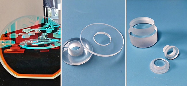
Drilled Spherical Lenses: Hole Axis Angle Causes More Trouble Than Hole Diameter
A hole typically serves one of two purposes: letting the optical path pass through, or letting a locating pin pass through. The two impose different requirements, but they share a common pitfall—the angular deviation between the hole axis and the lens optical axis. In a short path, a few tenths of a degree go unnoticed; in a large-aperture, long-focal-length system, even 0.1° of deviation can accumulate, through subsequent elements, into a spot shift that cannot be ignored. The way hole position tolerance is referenced to the lens optical axis in the drawing therefore warrants more attention than the hole diameter tolerance itself.
Material considerations diverge here. K9 is a mature process; hole dimensional consistency and wall finish are controllable under conventional grinding. Fused silica is harder—ultrasonic machining is viable but less efficient than K9, with a corresponding cost increase. Calcium fluoride's cleavage tendency makes mechanical drilling prone to micro-chipping at the hole entrance, requiring more conservative parameters or specialized methods. In calcium fluoride spherical lens work, we typically confirm hole-wall chipping acceptance criteria in advance for drilled features, because the edge condition of this material is not in the same reference frame as K9.
One variant easily overlooked in drawings: the drilled plano-concave spherical mirror. Light does not pass through the substrate, so hole-wall scattering does not affect the transmitted wavefront; however, whether the hole edge intrudes into the effective reflective aperture, and the coating coverage on the hole wall, must be defined separately.
Stepped Spherical Lenses: The Step Face Is the Axial Datum
Conventional assembly relies on the mount bore for centering and on retaining rings or spacers for axial positioning—every link adds to axial error, and the larger the aperture, the harder it is to hold. A stepped spherical lens machines a precisely defined step face in the non-clear aperture; during assembly it seats directly against the mount face, and axial position is determined by step depth. Step depth tolerance and the perpendicularity of the shoulder face to the optical axis replace a long chain of mechanical tolerances. Since large mount machining accuracy and cost are both rising, shifting the precision burden onto a feature that can be deterministically guaranteed at the optical fabrication stage is often the better trade. What customers care about most is usually not how many millimeters the step can be, but the depth tolerance band and the shoulder face figure—these two directly determine whether compensation shims are needed during assembly.
Material weighting differs from drilling here: the step is a large-area axial datum surface, so dimensional stability matters more than machinability. K9 has a relatively large thermal expansion coefficient—fine for room-temperature static use, but for thermal cycling the step depth variation must be included in the tolerance budget. Fused silica is an order of magnitude lower and is the safer choice in temperature-sensitive scenarios. Calcium fluoride also has a relatively high expansion coefficient and is softer, so edge protection on the step face requires extra attention in processing.
Edged Spherical Lenses: Centering Edging and Profile Edging Are Two Different Things
Centering edging aims to make the outer cylinder coaxial with the optical axis; the output is still a complete circular lens, merely ground to a precise outside diameter. Profile edging, by contrast, removes part of the edge after centering to form a non-circular aperture for rectangular packaging, array arrangement, or clearing mechanical interference. The process logic is entirely different: the former trues the outer diameter with reference to the optical axis, the latter removes a specified region with reference to the optical axis.
For large lenses, the challenge of edging is not the removal itself but whether the centering state of the remaining aperture is preserved. If clamping or cutting forces introduce new stress into an already polished lens, the figure may change slightly. Whether edging is placed before or after polishing therefore depends on the diameter-to-thickness ratio and figure tolerance requirements.
Float glass has its place in this category: for prototype validation or where wavefront requirements are not extreme, its cost advantage makes it a reasonable starting point; but once the system is formal and requires coating and long-term environmental stability, the substrate quality of K9 or fused silica pulls ahead. In delivery we generally recommend that customers specify at the drawing stage the profile dimensional tolerance, edge chipping allowance, and whether chamfering or edge polishing is required.
Drawing Callouts: Keep the Datum Consistent
All three shaping approaches share the same goal: reduce the intermediate links between lens and mount, and build alignment and positioning into the optical element itself.
The common drawing pitfall is the datum for feature position tolerances. The hole position, the step shoulder, and the profile contour must be referenced to the lens optical axis to serve as the basis for optical alignment. If they are called out to the substrate back face or outer diameter, fabrication may proceed fine, but the datum will not match at assembly. In drawing review we typically first confirm whether these features share the same optical-axis datum. Sharing means they can be completed in a single setup or tooling system, shortening the datum chain and keeping accumulated error controllable; if they are called out to different process datums, the conversation shifts to how to establish the conversion between them in the process flow. Many details here depend on the specific drawing, and we would not claim to have a ready answer for every case.
Material selection ultimately follows the stability of the datum chain: no need for fused silica when K9 suffices, avoid drilling calcium fluoride where possible, and let float glass appear only where it does not compromise datum accuracy.
Suggested Checks at the Drawing Stage:
Drilling: Is the angular tolerance between hole axis and optical axis defined? Do hole-wall chipping or micro-crack acceptance criteria match the material?
Step: Are depth tolerance and shoulder perpendicularity to the optical axis sufficient to replace the original mechanical adjustment?
Edging: Is the process sequence (before or after polishing) determined by diameter-to-thickness ratio and figure requirements? Does the edge need secondary treatment?
Datum consistency: Are all shaped features called out relative to the same optical-axis datum? If not, how is the conversion established in the process flow?
Zoolied Inc. is based in Changchun and provides custom fabrication of optical components and laser accessories. The discussion above on drilling, stepping, and edging in K9, fused silica, calcium fluoride, and float glass reflects experience accumulated in our daily work and may not cover every design scenario. If your drawing contains shaped features you are unsure about, we welcome the chance to align on acceptance criteria at the drawing stage—talking earlier is always more comfortable than discussing "can it be reworked" after the sample is made.
On Zoolied Inc.'s production line, inquiries for drilled, stepped, and edged spherical lenses often come down to the same question asked in different ways: "Can the lens solve its own positioning?"
Drilled Spherical Lenses: Hole Axis Angle Causes More Trouble Than Hole Diameter
A hole typically serves one of two purposes: letting the optical path pass through, or letting a locating pin pass through. The two impose different requirements, but they share a common pitfall—the angular deviation between the hole axis and the lens optical axis. In a short path, a few tenths of a degree go unnoticed; in a large-aperture, long-focal-length system, even 0.1° of deviation can accumulate, through subsequent elements, into a spot shift that cannot be ignored. The way hole position tolerance is referenced to the lens optical axis in the drawing therefore warrants more attention than the hole diameter tolerance itself.
Material considerations diverge here. K9 is a mature process; hole dimensional consistency and wall finish are controllable under conventional grinding. Fused silica is harder—ultrasonic machining is viable but less efficient than K9, with a corresponding cost increase. Calcium fluoride's cleavage tendency makes mechanical drilling prone to micro-chipping at the hole entrance, requiring more conservative parameters or specialized methods. In calcium fluoride spherical lens work, we typically confirm hole-wall chipping acceptance criteria in advance for drilled features, because the edge condition of this material is not in the same reference frame as K9.
One variant easily overlooked in drawings: the drilled plano-concave spherical mirror. Light does not pass through the substrate, so hole-wall scattering does not affect the transmitted wavefront; however, whether the hole edge intrudes into the effective reflective aperture, and the coating coverage on the hole wall, must be defined separately.
Stepped Spherical Lenses: The Step Face Is the Axial Datum
Conventional assembly relies on the mount bore for centering and on retaining rings or spacers for axial positioning—every link adds to axial error, and the larger the aperture, the harder it is to hold. A stepped spherical lens machines a precisely defined step face in the non-clear aperture; during assembly it seats directly against the mount face, and axial position is determined by step depth. Step depth tolerance and the perpendicularity of the shoulder face to the optical axis replace a long chain of mechanical tolerances. Since large mount machining accuracy and cost are both rising, shifting the precision burden onto a feature that can be deterministically guaranteed at the optical fabrication stage is often the better trade. What customers care about most is usually not how many millimeters the step can be, but the depth tolerance band and the shoulder face figure—these two directly determine whether compensation shims are needed during assembly.
Material weighting differs from drilling here: the step is a large-area axial datum surface, so dimensional stability matters more than machinability. K9 has a relatively large thermal expansion coefficient—fine for room-temperature static use, but for thermal cycling the step depth variation must be included in the tolerance budget. Fused silica is an order of magnitude lower and is the safer choice in temperature-sensitive scenarios. Calcium fluoride also has a relatively high expansion coefficient and is softer, so edge protection on the step face requires extra attention in processing.
Edged Spherical Lenses: Centering Edging and Profile Edging Are Two Different Things
Centering edging aims to make the outer cylinder coaxial with the optical axis; the output is still a complete circular lens, merely ground to a precise outside diameter. Profile edging, by contrast, removes part of the edge after centering to form a non-circular aperture for rectangular packaging, array arrangement, or clearing mechanical interference. The process logic is entirely different: the former trues the outer diameter with reference to the optical axis, the latter removes a specified region with reference to the optical axis.
For large lenses, the challenge of edging is not the removal itself but whether the centering state of the remaining aperture is preserved. If clamping or cutting forces introduce new stress into an already polished lens, the figure may change slightly. Whether edging is placed before or after polishing therefore depends on the diameter-to-thickness ratio and figure tolerance requirements.
Float glass has its place in this category: for prototype validation or where wavefront requirements are not extreme, its cost advantage makes it a reasonable starting point; but once the system is formal and requires coating and long-term environmental stability, the substrate quality of K9 or fused silica pulls ahead. In delivery we generally recommend that customers specify at the drawing stage the profile dimensional tolerance, edge chipping allowance, and whether chamfering or edge polishing is required.
Drawing Callouts: Keep the Datum Consistent
All three shaping approaches share the same goal: reduce the intermediate links between lens and mount, and build alignment and positioning into the optical element itself.
The common drawing pitfall is the datum for feature position tolerances. The hole position, the step shoulder, and the profile contour must be referenced to the lens optical axis to serve as the basis for optical alignment. If they are called out to the substrate back face or outer diameter, fabrication may proceed fine, but the datum will not match at assembly. In drawing review we typically first confirm whether these features share the same optical-axis datum. Sharing means they can be completed in a single setup or tooling system, shortening the datum chain and keeping accumulated error controllable; if they are called out to different process datums, the conversation shifts to how to establish the conversion between them in the process flow. Many details here depend on the specific drawing, and we would not claim to have a ready answer for every case.
Material selection ultimately follows the stability of the datum chain: no need for fused silica when K9 suffices, avoid drilling calcium fluoride where possible, and let float glass appear only where it does not compromise datum accuracy.
Suggested Checks at the Drawing Stage:
Drilling: Is the angular tolerance between hole axis and optical axis defined? Do hole-wall chipping or micro-crack acceptance criteria match the material?
Step: Are depth tolerance and shoulder perpendicularity to the optical axis sufficient to replace the original mechanical adjustment?
Edging: Is the process sequence (before or after polishing) determined by diameter-to-thickness ratio and figure requirements? Does the edge need secondary treatment?
Datum consistency: Are all shaped features called out relative to the same optical-axis datum? If not, how is the conversion established in the process flow?
Zoolied Inc. is based in Changchun and provides custom fabrication of optical components and laser accessories. The discussion above on drilling, stepping, and edging in K9, fused silica, calcium fluoride, and float glass reflects experience accumulated in our daily work and may not cover every design scenario. If your drawing contains shaped features you are unsure about, we welcome the chance to align on acceptance criteria at the drawing stage—talking earlier is always more comfortable than discussing "can it be reworked" after the sample is made.